Case Study on the Measurement of Tiny Turbine Blades
WENZEL Measuring Machines (Shanghai) Co.,Ltd
[Keyword]: Tiny blade, optical measurement, incident angle, blade deformation
The aero engine is one of the most critical components that uses the most complicated technologies and with the highest manufacturing difficulty in the aircraft. For example, the typical turbofan engine consists of 1 stage of fan section, 13 - 14 stages of compressor section and 8-9 stages of turbine section, which includes up to thousands of blades in total. The blade height differs greatly from nearly 1000mm of the fan blade to less than 20mm of the blade of the high-pressure compressor at the final stage.
As for the processing and measurement of them, a blade with the maximum or minimum dimension will undoubtedly bring forth a greater challenge. They cause the processing and measuring equipment as well as their methods to be subjected to tougher requirements. This case conducted a test on measuring one typical tiniest blade used in the aircraft engine, verified the feasibility and effects of a certain type of optical measuring equipment to measure the profile of the tiniest blade and theoretically compared it with several other measuring methods.
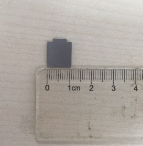
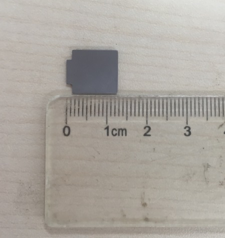
[Actual photo of blade]
Measurement difficulties
It can be seen from the Figure above that the blade has an overall height of about 13mm, a profile width of about 11mm and the maximum thickness at the blade center is about 1mm. It belongs to the tiniest type of the aircraft engines. Especially, the edge of the blade is only about 0.2mm thick, which causes many difficulties for measurement:
-
First, the blade size is too small, thus bringing about a very great difficulty for clamping. The clamping will cause instability if on too small an area and lead to interference if on too big an area.
-
Second, it will be a great challenge to select the probe if a method of contact measurement is employed. For the thinnest blades, if a big measuring ball is used, it will get stuck when measuring the leading and trailing edges and tends to cause interference. If a small measuring ball is used, it tends to generate an error of the radius compensation direction and results in the phenomenon of inordinate profile.
-
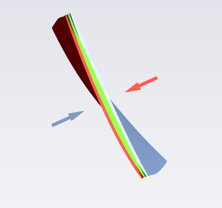
Moreover, these thinnest blades tend to be bent slightly by the measuring force when the cross-section on the top is measured (as shown in the following Figure that: when the blade basin is measured, the blade is bent toward the back by the measuring force and vice versa.) Although the deformation of bending is not big, in consideration of the thinnest thickness of the blade, its relative degree of deformation is rather considerable and will greatly affect the profile tolerance and the position tolerance of the profile tested.
Potential issues of optical measurement
If an optical probe is used to scan such blade, it must have very high resolution and scan an adequate density of points on the leading and trailing edges at the positions with abrupt change of curvature. Only in this way, the shape of the leading and trailing edges can be truly represented and hence the parameters related to the blade profile can be analyzed accurately.
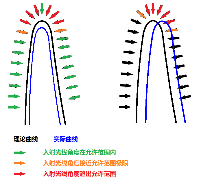
First, an optical probe usually has a requirement on the surface conditions of an object. A surface that is too bight or has too deep color will negatively affect the light reflection. Second, the particularity of the geometrical shape of such blade has a certain requirement on the working distance of the optical probe. Some types of optical probes can realize a high measuring accuracy, but they need a very short working distance, thus it is very easy to result in collision with the blade. Nevertheless, if the lens is changed to give a wider working distance, the measuring accuracy will be obviously reduced. Third, it needs to note the range of incident angle on the surface. During the measurement of a component, if the direction of normal line is always used to take a point, it is inevitable to generate a dead zone. Thus, the vector direction of the incident light needs to be modified in this case. If the incident angle allowed by the optical probe has a narrow range, it will be inconvenient for measuring.
Especially when the leading and trailing edges are measured, because an unavoidable shape and/or position deviation exists between the actual profile and the theoretical model, the direction of incident light set by a theoretical model cannot form an orthogonality with the actual profile. The wider the angle of incident light allowed by the probe is, the better the fault tolerance of the probe to the light is. Otherwise, even a slight deviation of the angle of incident light may cause the probe to fail to receive the reflected light signal, which results in the missing of measure points.
WENZEL's optical measurement solution of blade -CORE
CORE white light blade measuring system is a non-contact spot-scanning optical measuring equipment. The special design and optimization are incorporated on blade measurement in terms of hardware and software. The white light point probe of CORE-DS uses a white light as the light source. Compared with the contact methods, it provides higher resolution. It uses a spot size of only 35µm, which can detect the tiniest geometrical features and a defect on the surface of test object, especially suitable to measure the leading edge and trailing edge of the blade. CORE uses the white light probe. It can avoid the probe radius compensation error that is easy to occur during blade measurement by a contact probe and hence realize a more accurate measuring result. Compared with other optical measuring equipment, the white light probe of CORE-DS has very high applications to various object surfaces and can directly measure without conducting any treatment on the surface. The objects measurable include a highly bright surface, black surface and even an object with a mirror surface. Moreover, the angle between the light and the object is allowed to be as low as 5°.
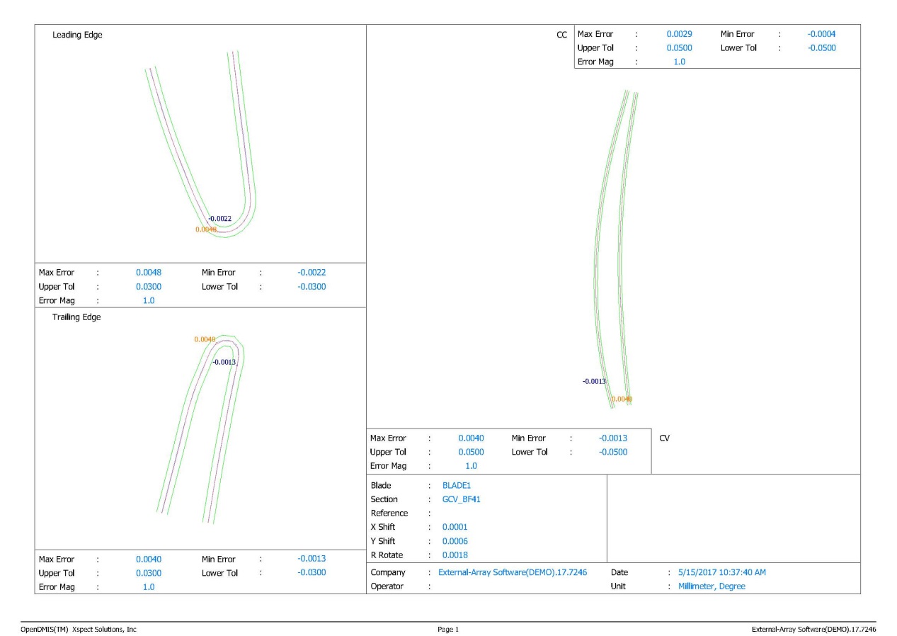
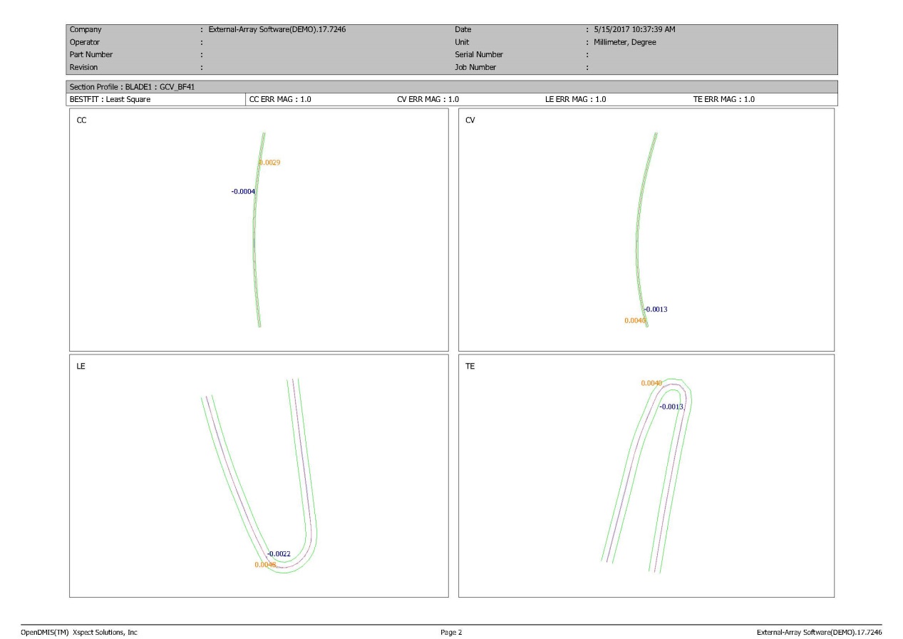
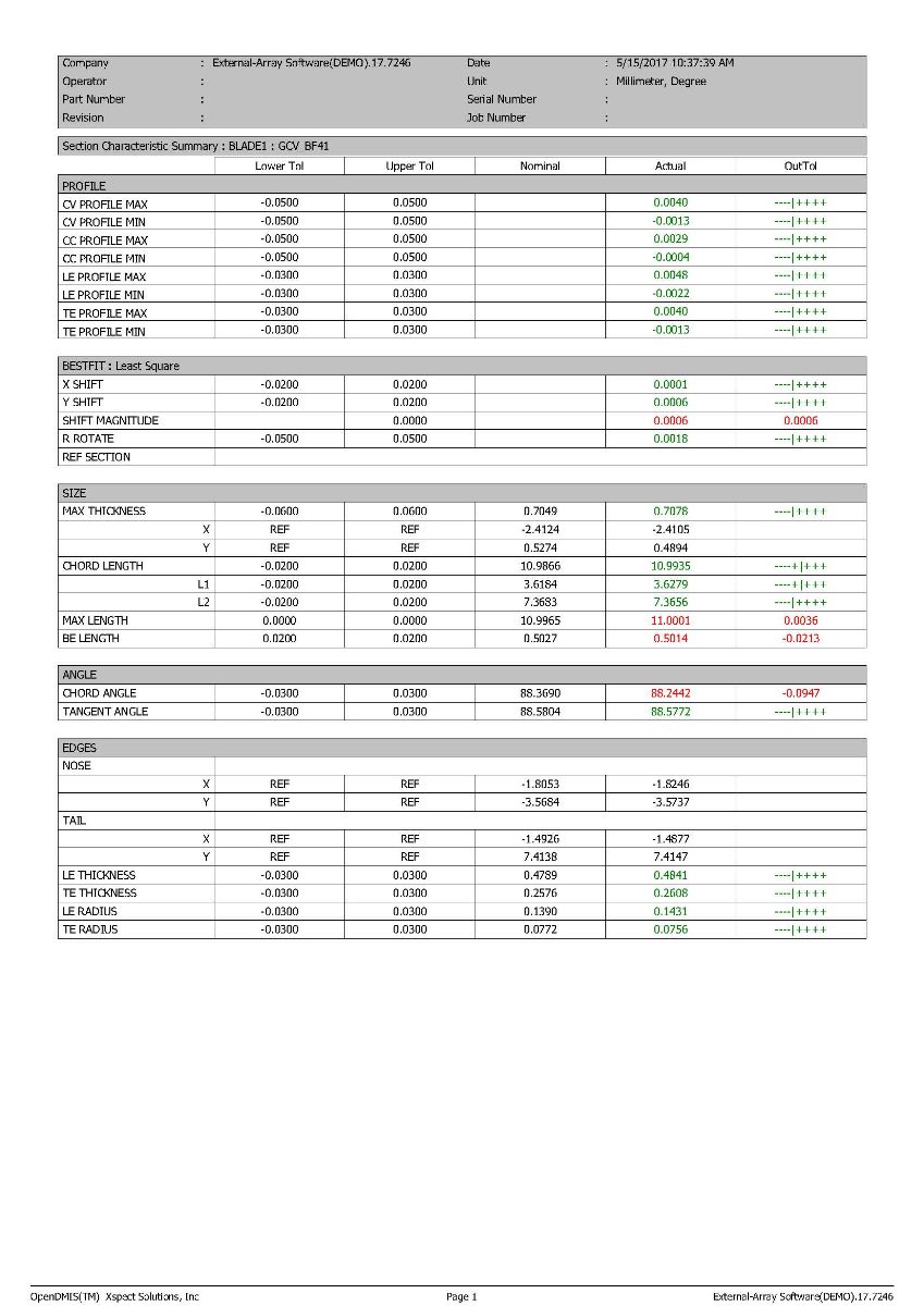
As shown in the measuring results, the maximum thickness of the blade is 0.7mm, the maximum chord length is 11mm and the radius of the trailing edge is only 0.075mm. The measuring results demonstrates that CORE can measure the tiniest blades and provide an outstanding performance compared with the contact probes and other optical probes.